Rocket Structure
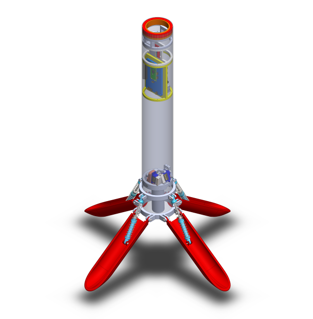
Thrust Vector Assembly
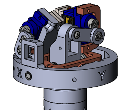
The thrust vector assembly is the mechanical system that physically turns the motor (and thus the thrust) relative to the rocket body. This allows us to control the rocket's attitude and velocity.
Design Facts
Design DecisionsDesigned with the intent of being as future proofed as possible, taking all our requirements and outperforming in every way possible. One of the largest ranges of motion of any model TVC, use of 4-bar linkages to increase the mechanical advantage of the servos, modular design with optional closed-loop control with potentiometers, and universal motor adaptor for customizable motor selection and throttling.
|
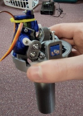
Design ProcessThe design revolves around the 4-bar linkage control system that was given an initial design which quickly evolved to meet the force and space requirements of the rocket. Servos were chosen based on their availability and fitted to the 4-bar linkage in a way that allowed us to reach the 10 degree range of motion of the motor while still conforming to the rocket body space requirements as closely as possible. The final design does protrude slightly from the body, however it can be avoided by limiting the range of motion of the TVC if the user would like.
ResultsWas the first TVC model to demonstrate stability during one-axis stability testing and demonstrated control of the rocket during the first drop test conducted by the team with no signs of failure or damage to the system even after falling unprotected to the ground from the drop height twice. The system also withstood the violent ejection charge of Estes D-class motors without issue further proving the design's success.
|
Center of Mass Aligner
Our analysis found that steady-state error in our attitude control was closely correlated with the mass imbalance. We created a mass-alignment device to align the rocket's center of mass.
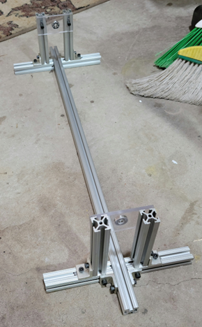
Design OverviewRocket is mounted along its central axis turning it into a “shaft” that can be balanced by rotating the whole rocket and allowing the heaviest part to settle at the bottom. Weights are added to the opposite side and the process is repeated until the rocket spins freely
Design FactsAble to accommodate full length of rocket with landing legs attached.
|
Design ProcessInspiration taken from the FSAE tire balancer that was found in our workspace before we moved in! Took this concept and accommodated it for our rocket body. At first, the landing legs were not able to fit in the assembly but utilizing a more modular design with aluminum extrusion allows the design to accommodate the rocket now and in future designs.
ResultsSuccessfully able to balance the rocket with the assembly and has been used prior to stability and landing tests.
|
